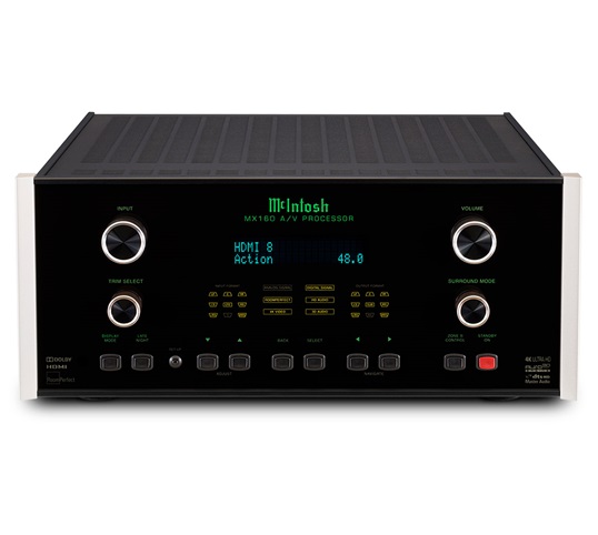
Download Free Mcintosh Mx151 Manual
вторник 19 марта admin 43
• McIntosh Laboratory, Inc. 2 Chambers Street Binghamton, New York Phone: 607-723-3512 www.mcintoshlabs.com MX121 A/V Control Center Owner’s Manual. • The lightning flash with arrowhead, within an equilateral The exclamation point within an equilateral triangle is triangle, is intended to alert the user to the presence of intended to alert the user to the presence of important uninsulated “dangerous voltage” within the product’s en- operating and maintenance (servicing) instructions in the closure that may be of sufficient magnitude to constitute literature accompanying the appliance. Patents and that is protected by U.S.
McIntosh Debuts MX121 and MX151 AV Control Centers. McIntosh Laboratory is ready to rock — a little bit harder, apparently. Download our FREE Guides to help you better plan for.
Patents and other intellectual trade dress are trademarks or registered trademarks of other intellectual property rights. The MX121 uses the property rights of Rovi Corporation. Reverse engi- Pandora Media, Inc. Used with permission.
• Thank You Customer Service Front Panel: Your decision to own this McIntosh MX121 A/V Con- If it is determined that your McIntosh product is in trol Center ranks you at the very top among discrimi- need of repair, you can return it to your Dealer. You Front Panel Displays, Controls and Push-buttons.147. • Output and a TV/Monitor, the On-Screen Over- each HDMI Source connected to MX121. The Main AC Power going to the MX121 and lays including Menus, will only appear on the 9. The Main Zone accepts Video Input Signals from any other McIntosh Component(s) should not HDMI Output. • Connector and Cable Information XLR Connectors Below is the Pin configuration for the XLR Balanced RS232 DB9 Connector Pin Layout Output Connectors on the MX121.
Refer to the dia- 1. N/C grams for connections: 2. Data Out (TXD) 7. • Digital EX, DTS Neo6 and DTS-ES Sound Tracks. • Triple Zones • Internet Streaming The MX121 has the built-in ability to control a sepa- Performance Features The MX121 when connected to a network, offers In- rate remote audio/video zone (Zone 2) with program •. • Dimensions Dimensions The following dimensions can assist in determining the best location for your MX121.
Front View of the MX121 ' 44.5cm ' ' 19.4cm 18.1cm Side View of the MX121 ' 41.9cm ' 36.8cm ' 9/16 ' 3/16 16.7cm 0.5cm. • Installation Installation The MX121 can be placed upright on a table or ' 3/16 shelf, standing on its four feet. It also can be custom 43.7cm installed in a piece of furniture or cabinet of your choice.  The four feet may be removed from the bottom of the MX121 when it is custom installed as outlined below.
• Rear Panel Connections Rear Panel Connections The identification of Rear Panel Connections for the MX121 A/V Control Center is located on a separate folded sheet contained in the Owner’s Manual Packet. Refer to separate sheet “Mc1A” for the Rear Panel Connections.
Connect a Ground Cable from the MX121 GND external sensor connected, remote control operation of the system is possible when the MX121 is located in a nection Block) to the MX121 IR IN Jack. Binding Post to the Turntable GND Binding Post. • When Zone 2 (Audio/Video in another room) on the Power Amplifier Three Power Control In Jack.
MX121 will be utilized, proceed to page 13 for infor- 4. Connect a Control Cable from Main Zone Power mation on making the needed additional connections. • Note: If there is no external Sensor used for the Main Zone, a splitter is not needed. Connect For additional information refer to “Connector and the Zone 2 Sensor directly to the MX121 IR IN Cable Information” on page 6. • Front Panel Display, Controls, and Push-buttons Front Panel Display, Controls, and Push-buttons The identification of the MX121 A/V Control Cen- ter Front Panel Display, Controls, and Push-buttons is located on a separate folded sheet contained in the Owner’s Manual Packet. Refer to separate sheet “Mc1B”. • Remote Control Push-Buttons Remote Control Push-Buttons The identification of Remote Control Push-Buttons for the MX121 A/V Control Center is located on a separate folded sheet contained in the Owner’s Manual Packet.
Refer to separate sheet “Mc4A and Mc4B” for Push- buttons identification. • Manual Setup To assist in navigating the various On Screen Input Setup Menus please refer to the set of MX121 Menu separate folded sheets 'MX121-Menu-1 thru Menu-7'; and to separate sheets “Mc4A thru Mc4B” for Push-button identifications.
